|
February 14/2000 - Build Update 3 I've had a busy 2 weeks, and I hope you have too. I made some good progress and I started on the electronics, so I'm in good shape. I have decided to try to get the robot under the 87 lb weight limit for Bot Bash 2000 in Arizona (provided I have a car by then too). This will be without the smashy axe (the intended weapon) though, as I just can't keep it under 87 lbs with it on. I'll have to think up a light weight weapon for the event. In other news, I just found out that my site is the 348th most visited site under my school's server. We can do better though -- keep on visiting and boost those stats! Until next time... - Derek. Suggested Listening During Early February Robot Building: The Dead Kennedys - Fresh Fruit for Rotting Vegatables The Slackers - Better Late Than Never Guns n' Wankers - Self Titled |
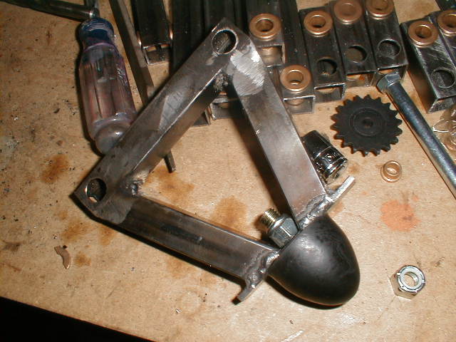
| As promised last time, I attached the ES robot feet to the legs. I welded a 3/4" wide piece of .125" thick steel across the bottom of the leg and bucked a hole in the middle. Super simple, strong and easy to change feet. I trimmed the ends off them BTW. |
|
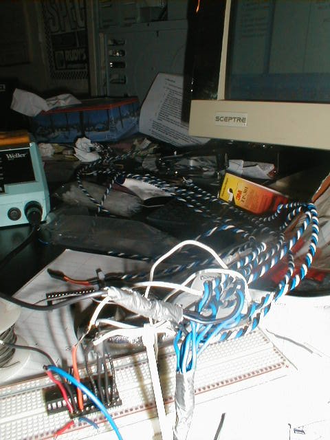
A close up of my electronics development setup ;). I'm done writing all the code for my linear actuator control system, but it turns out my PICSTART plus doesn't have current enough firmware to program the fancy 16F873 PICs that I bought. I hope to get to debugging this week sometime. |
|
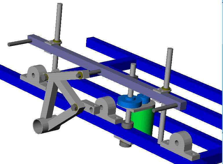
This is a SolidWorks drawing of the original idea for making the "ground bar" travel up and down in a consistant manner. As I found out quickly, that which can be drawn and simulated on SolidWorks, is not always possible in real life. This design, involving 1/2" steel rods and bronze bushings to ride up and down on the rods, was implemented last time but it binded too much and I had to do some re-thinking. |
|
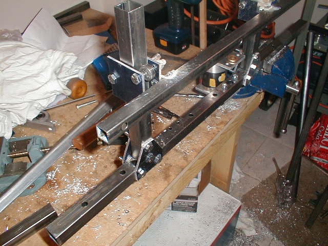
Solution #2, to have 2 lead screws move the ground bar up and down. This way, there should be no binding at all, right? Wrong! The two acme nuts that I welded to the bar were impossible to align with one another. This was almost worse than the first design. |
|
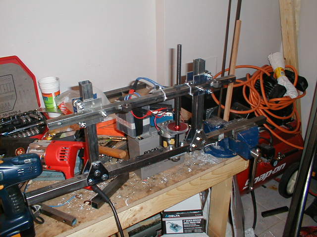
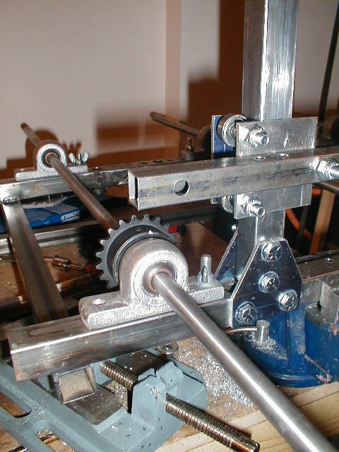
Solution #3. This time, I made my own ball bearing slides that ride up and down on 1" square tubing. The slides worked great on their own, but when I attached the bar between the two: nothing. I was pretty fed up at this point, but I had one trick left up my sleve... |
|
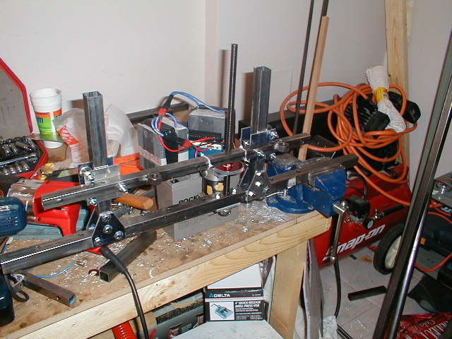
Solution #3b. Turn them around! I oriented them 90 degrees from the original mounting position and attached the bar by 2 points, allowing for mis-alignment. It worked! Bar goes up... |
|
...bar goes down. All by R/C using my Vantec RDFR22. Cool! The control system will eventually do position control with these things, so it will be like a servo, command a position, it goes there. |
|
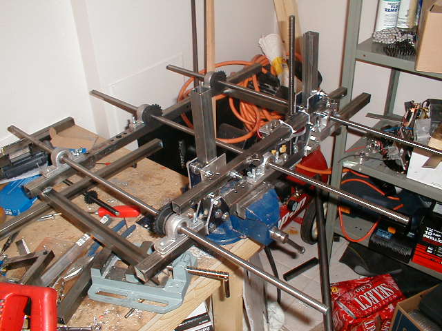
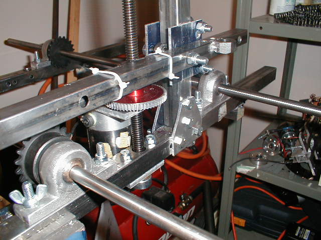
I was so happy about my success that I went ahead and started welding up the ladder frame. Quick and easy. I also picked up some 1/2" water hardened drill rod for axles. Anybody know how to drill into this stuff? Also shown are the 35 pitch drive sprockets. |
|
A close up of the actuator/ground bar connection. The cable ties are just temporary. Lurking behind them is the acme nut with a length of steel plate welded on so there is a non-solid connection between the bar and the nut. |
|
Another close up. Here you can see the linear slide and the brackets I made to attach the 1" tubing to the frame. I would have welded it, but it needs to be adjustable to allow for proper alignment of the two sliders. I'm re-using pillow blocks from Son of Smashy. |
|
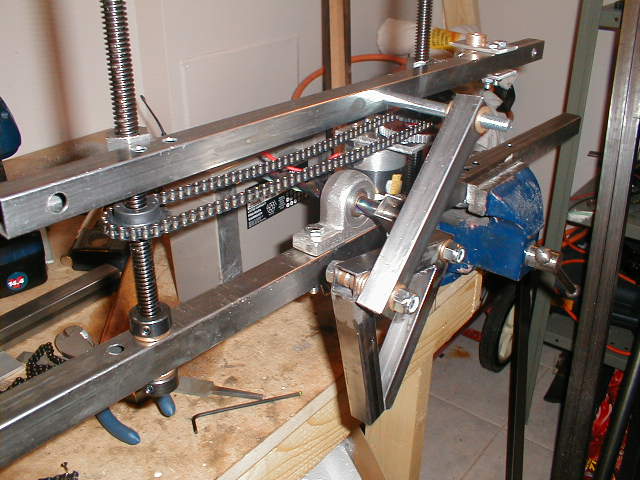
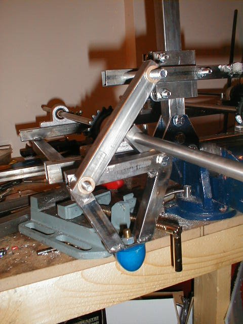
I couldn't resist test mounting the leg again, so here it is! -- Next up is repeating the sliders on the other side and assembling the chains for the drivetrain. |
|